

Selecting the right cooling solution requires more than just picking a fan that fits a housing. In the world of thermal management, the relationship between axial fan airflow and static pressure determines whether a system operates at peak efficiency or suffers from premature component failure. For engineers and OEM project managers, understanding the “Fan Curve” is the difference between a high-performance design and a costly redesign.
The Physics of Axial Flow
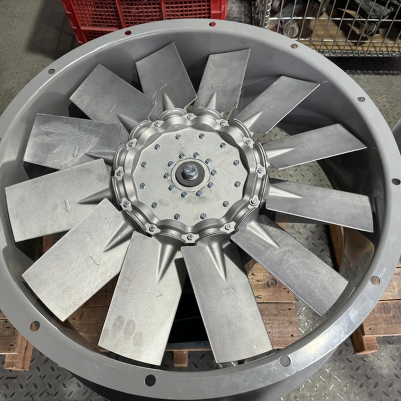
An axial fan moves air along the axis of the fan’s rotation. Unlike centrifugal fans that deflect air at a 90-degree angle, axial fans use aerodynamic blades to create a pressure difference. This pressure difference forces air through the fan blades, moving it parallel to the shaft.
The primary advantage of this design is the ability to move high volumes of air (high CFM) at relatively low back-pressure. This makes them ideal for applications ranging from server rack cooling to industrial ventilation. However, the performance of an axial fan is never a single fixed value; it is a dynamic relationship influenced by the environment in which the fan operates.
Decoding the P-Q Curve: Airflow vs. Static Pressure
To evaluate axial fan airflow, engineers use the P-Q curve (Pressure-Flow curve). This graph illustrates how the fan performs as it encounters resistance.
- Airflow (Q): Usually measured in Cubic Feet per Minute (CFM) or Cubic Meters per Hour (m³/h). This represents the volume of air moved when there is zero resistance.
- Static Pressure (P): Usually measured in inches of water gauge (inH₂O) or Pascals (Pa). This represents the resistance or “back-pressure” the fan must overcome, such as filters, grills, or densely packed heat sinks.
The curve typically starts at the “Free Air” point (maximum airflow, zero pressure) and ends at the “Shut-off” point (zero airflow, maximum pressure). In real-world applications, a fan never operates at either extreme. It operates at an “Operating Point” where the fan’s performance curve intersects with the system’s resistance curve.
The Impact of System Resistance
Every object placed in the path of the airflow—finger guards, dust filters, PCBs, or complex ductwork—creates resistance. This is known as the System Impedance.
When designing a cooling system, the goal is to calculate the system impedance curve, which typically follows a square law: if you want to double the airflow, the required pressure increases by four times. If the system impedance is too high, the axial fan airflow will drop significantly, leading to heat buildup.
In high-density environments, such as telecom enclosures or power supplies, engineers often transition from standard AC fans to high-performance EC or DC axial fans, which offer higher torque and more aggressive blade pitches to overcome significant static pressure.
Identifying and Avoiding the Stall Region
One of the most critical technical aspects of axial fan performance is the “Stall Region” (sometimes called the “Dip” in the P-Q curve).
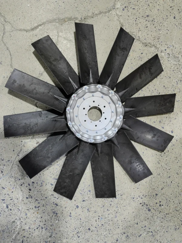
As the static pressure increases, the air may begin to separate from the suction side of the fan blades. This creates turbulence and a sudden drop in pressure-generating capability. Operating a fan in this stall region leads to:
- Increased acoustic noise (vortex shedding).
- Decreased efficiency.
- Excessive vibration, which can shorten the bearing life.
Expert design requires ensuring that the operating point stays to the right of the stall region, where the airflow remains laminar and stable.
Technical Comparison: Performance Factors
| Feature | Impact on Airflow | Impact on Static Pressure |
| Blade Pitch (Angle) | Higher pitch increases volume at low pressure. | Higher pitch can increase stall risk at high pressure. |
| Blade Count | More blades generally increase pressure capability. | High blade counts may increase noise levels. |
| Rotational Speed (RPM) | Airflow increases linearly with RPM. | Static pressure increases by the square of the RPM. |
| Housing Design | Tight tip clearance reduces air leakage. | Proper shrouding increases overall static efficiency. |
Application-Specific Performance Logic
The choice of axial fan depends heavily on the “impedance profile” of the application:
- Ventilation and Exhaust: These systems usually have low resistance. The priority is maximizing volume (CFM). Large-diameter axial fans with high airflow ratings are preferred here.
- Electronics Cooling: Densely packed server blades or power inverters create high resistance. In these cases, the fan must have a “steep” curve—meaning it maintains significant airflow even as the pressure rises.
- Outdoor Industrial Equipment: Factors like ingress protection (IP ratings) and the use of heavy-duty filters significantly increase the pressure load. This requires industrial-grade axial fans designed with high-torque motors to maintain consistent airflow through dirty filters.
Engineering Considerations for Optimal Airflow
Beyond the fan itself, the installation environment dictates performance. To maximize axial fan airflow, consider these manufacturing and design constraints:
- Inlet Obstructions: Placing a component too close to the fan inlet creates non-uniform flow, which can reduce airflow by up to 30%. A rule of thumb is to maintain a gap at least 50% of the fan’s depth.
- Air Leakage: In high-pressure systems, any gap between the fan housing and the mounting surface allows air to “recirculate” back to the intake, drastically reducing cooling efficiency.
- Fan Laws: If you need to adjust performance after the prototype stage, remember the Fan Laws. Doubling the RPM will double the airflow, but it will also increase the power consumption by a factor of eight (cube law).
Matching Performance to Hardware
When sourcing components for OEM projects, it is essential to match the fan’s voltage and drive type to the system’s thermal management strategy. Modern axial fans are available in AC, DC, and EC (Electronically Commutated) variants.
EC fans are particularly valued in modern industrial design because they combine the ease of AC power with the controllable performance of DC motors. This allows for pulse-width modulation (PWM) control, enabling the fan to speed up or slow down based on real-time temperature sensors, effectively managing the airflow-to-pressure ratio on demand.
FAQ
What is the difference between Free Airflow and the Operating Point?
Free Airflow is the maximum volume of air a fan can move when there are no obstructions (zero static pressure). The Operating Point is the actual amount of air the fan moves once it is installed inside a device and encounters resistance from components and filters.
How does altitude affect axial fan airflow?
As altitude increases, air becomes less dense. While the volume of air moved (CFM) remains relatively constant, the mass of the air decreases, which reduces the cooling capacity. Engineers must often “over-spec” fans for equipment destined for high-altitude environments.
Why is my fan making more noise than the datasheet suggests?
Datasheet noise levels are measured in “Free Air” conditions. If a fan is operating near its stall region or against high static pressure, turbulence increases, which significantly raises the decibel level.
Can I run two axial fans in series to increase airflow?
Running fans in series (stacked) does not significantly increase airflow; instead, it increases the static pressure capability. To increase total airflow, fans should be placed in parallel (side-by-side).
Reference Sources
- AMCA (Air Movement and Control Association): Standard 210, “Laboratory Methods of Testing Fans for Aerodynamic Performance Rating.”
- ISO 5801: Industrial fans — Performance testing using standardized airways.
- ASHRAE Handbook: Fundamentals of HVAC systems and air movement physics.
- IEEE Xplore: Research on “Aerodynamic Optimization of Axial Flow Fans for Electronics Cooling.”