

The efficiency of an industrial ventilation system is rarely the result of a single component. Instead, it is the product of mechanical synergy between three core elements: the blade, the hub, and the bushing. In the context of high-performance axial fans, these parts must withstand significant centrifugal force, thermal fluctuations, and aerodynamic stress.
For engineers and project managers, understanding the nuances of axial fan parts is not just about maintenance; it is about optimizing the “Specific Fan Power” (SFP) and ensuring the structural integrity of the entire HVAC or cooling assembly. This guide breaks down the technical specifications and functional logic of the primary components that constitute an axial impeller.
1. The Blade: Aerodynamics and Material Science
The blade is the primary interface between the mechanical energy of the motor and the kinetic energy of the air. Its design dictates the airflow volume (CFM) and the static pressure capability of the fan.
Aerfoil vs. Sickle Designs
Most industrial axial fan blades utilize an airfoil (wing-shaped) profile. This design creates a pressure differential that “lifts” the air, moving it parallel to the fan axis.
- Airfoil Blades: Ideal for high-efficiency requirements in cooling towers and radiators.
- Sickle Blades: Often used to reduce noise profiles in condenser units due to their graduated leading edge.
Material Integrity
Selecting the right material for fan blades involves balancing weight, stiffness, and environmental resistance.
- Glass-Reinforced Polyamide (PAG): Preferred for its high strength-to-weight ratio and resistance to corrosion. It is commonly found in engine cooling and general ventilation.
- Aluminum Alloy: Essential for high-temperature environments or applications requiring spark resistance (ATEX environments).
- Steel/Stainless Steel: Reserved for heavy-duty industrial processing where abrasion or extreme chemical exposure is a factor.
The Role of Pitch Angle
The pitch—the angle at which the blade is set relative to the plane of rotation—determines the fan’s performance curve. A higher pitch increases airflow but requires more torque (horsepower) from the motor. Modular axial fan systems, such as those found in professional axial fan part inventories, allow for adjustable pitch angles, enabling the same hub assembly to be fine-tuned for different static pressure requirements.
2. The Hub: The Structural Core
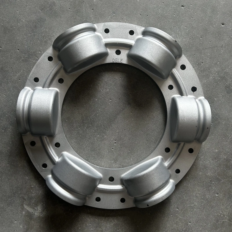
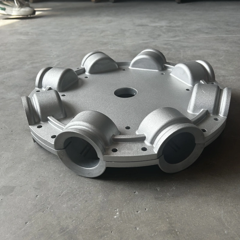
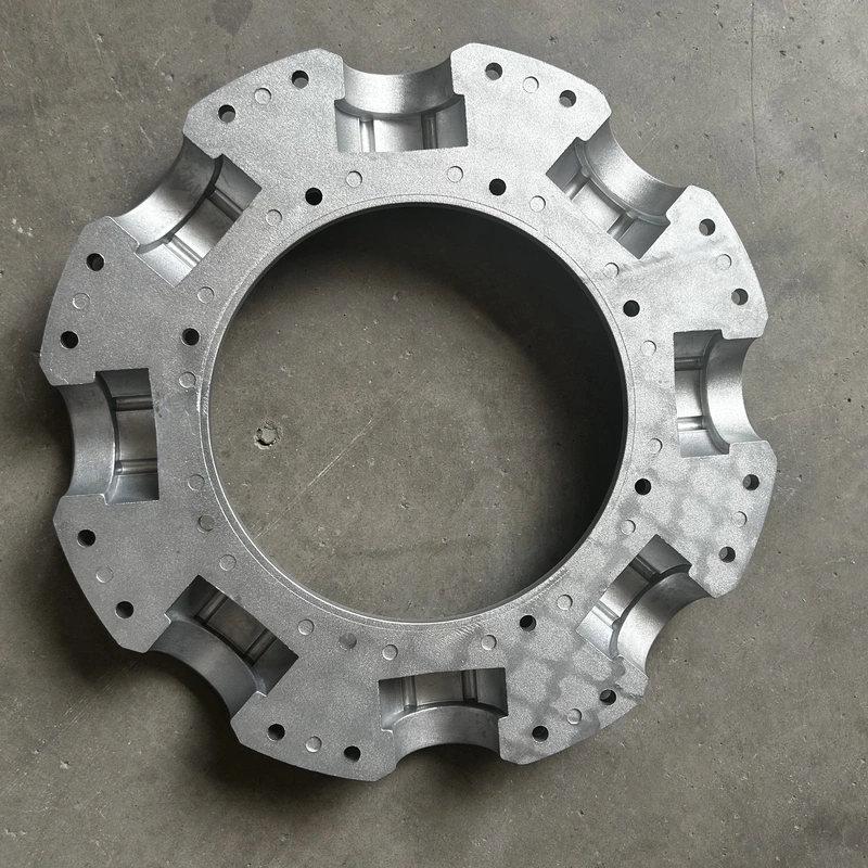
If the blades are the “wings,” the hub is the “chassis.” The hub’s primary function is to secure the blades at a precise orientation while transferring rotational torque from the drive shaft.
Structural Dynamics
Hubs are typically manufactured through high-pressure die-casting (for aluminum) or precision machining. The engineering of a hub must account for:
- Blade Root Compression: The hub must grip the blade root with enough force to counteract centrifugal loads that can reach several tons at high RPMs.
- Dynamic Balance: An unbalanced hub leads to vibration, which can destroy motor bearings and cause fatigue failure in the blades. High-quality hubs are balanced according to ISO 1940 standards (typically G6.3 or G2.5).
Modular vs. Fixed Hubs
Modern industrial fans often move away from “one-piece” cast impellers in favor of modular hub assemblies. Modular hubs allow for the replacement of individual blades rather than the entire unit, significantly lowering Total Cost of Ownership (TCO). This modularity also facilitates the use of different blade materials on the same hub design to meet specific environmental needs.
3. The Bushing: The Critical Connection
The bushing (or mounting bush) is perhaps the most underrated component of the axial fan assembly. It serves as the interface between the fan hub and the motor shaft.
Taper-Lock vs. Parallel Bores
The method by which the fan is secured to the shaft determines the ease of maintenance and the security of the fit.
- Tapered Bushings (e.g., Taper-Lock or QD): These use a split-sleeve design. As the bolts are tightened, the bushing contracts around the shaft, creating a high-friction “shrink-fit” that eliminates shaft play. This is the industry standard for high-vibration industrial applications.
- Straight Bores with Keyways: Common in smaller or budget-sensitive applications. They rely on a key and set screws to transmit torque. While simpler, they are more prone to “fretting corrosion” if the fit is not perfectly machined.
Dimensional Precision
Bushings must be machined to tight tolerances. A mismatch of even 0.05mm in the bore size can lead to catastrophic failure at high speeds. When selecting axial fan bushings, engineers must verify the shaft diameter, keyway dimensions, and the specific taper series compatible with the hub.
Component Comparison Table: Industrial Axial Fan Parts
| Component | Primary Function | Common Materials | Key Engineering Metric |
| Blade | Air displacement & pressure generation | PAG, Aluminum, PAGAS | Pitch Angle & Lift-to-Drag Ratio |
| Hub | Centrifugal load distribution | Die-cast Aluminum, Steel | ISO 1940 Balance Grade |
| Bushing | Shaft-to-Hub torque transfer | Cast Iron, S45C Steel | Bore Tolerance & Clamp Force |
4. System Synergy: How Parts Work Together
The performance of an axial fan is a “weakest link” scenario. If you have an aerodynamically perfect blade but a hub with poor dynamic balance, the resulting vibration will lead to premature motor failure.
In a typical assembly workflow:
- The Bushing is seated onto the motor shaft, ensuring the keyway is aligned.
- The Hub is fitted over the bushing. As the fastening bolts are torqued, the bushing locks the hub into a centered position.
- The Blades are inserted into the hub sockets. In adjustable-pitch models, the angle is set using a protractor before the final clamping force is applied to the hub halves.
This modular approach, common in the Colorfan axial fan parts range, allows for maximum flexibility. For instance, a technician can swap out PAG blades for Aluminum blades if a fan is moved from a standard ventilation duct to a high-heat drying kiln, all while utilizing the same hub and bushing infrastructure.
5. Technical Selection Considerations
When specifying axial fan parts for OEM or replacement projects, consider the following “Real-World” constraints:
- Tip Speed: As the fan diameter increases, the speed at the tip of the blade can approach the speed of sound. This requires blades with high structural stiffness to prevent “flutter.”
- Corrosion Zones: In coastal or chemical processing plants, even the bushing must be treated (e.g., phosphating or zinc plating) to prevent the assembly from seizing onto the shaft.
- Inlet Conditions: Turbulence at the fan inlet can cause uneven loading on the blades. Choosing a hub with high dampening characteristics can help mitigate the transfer of these stresses to the motor.
FAQ
Q1: Can I mix and match blades from different manufacturers on one hub?
A: Strictly no. The blade root design and the hub socket geometry are proprietary. Mixing parts can lead to mechanical failure and voids all safety certifications. Always source blades, hubs, and bushings as a validated system.
Q2: What is the benefit of a glass-reinforced polyamide (PAG) blade over aluminum?
A: PAG is lighter, which reduces the “Moment of Inertia.” This allows the motor to reach full speed faster and reduces wear on the starter and bearings. It is also naturally resistant to many chemicals that would corrode aluminum.
Q3: How do I know if my fan hub requires rebalancing?
A: If you notice increased noise (low-frequency humming), visible vibration of the motor housing, or premature bearing failure, the assembly should be checked. If any single blade is replaced, the entire impeller assembly must be dynamically rebalanced.
Q4: Does the bushing size affect the fan’s RPM limit?
A: Indirectly. The bushing must be rated for the torque and speed of the application. High-speed fans typically require precision-ground tapered bushings to ensure perfect concentricity, which minimizes centrifugal imbalance at high RPMs.
Reference Sources
- AMCA Publication 211: Certified Ratings Program – Product Rating Manual for Fan Air Performance.
- ISO 1940-1: Mechanical vibration — Balance quality requirements for rotors in a constant (rigid) state.
- Engineering Toolbox: Axial Fan Law and Performance Curves.
- VDI 2044: Performance testing of fans (Association of German Engineers).