

To properly size a diesel generator cooling fan, engineers calculate the precise Cubic Feet per Minute (CFM) required to extract combustion heat, balanced against the radiator’s static pressure impedance. Successful OEM supply requires matching blade pitch, diameter, and material specifications to the engine’s parasitic load limits. This is followed by a structured RFQ process to validate factory tooling and mass-production capacity. Overlooking these parameters results in either catastrophic thermal failure from undersizing or wasted fuel from excessive aerodynamic drag.
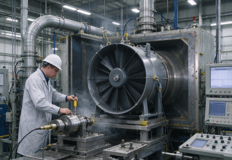
Airflow Calculations and Static Pressure Impedance
Generating continuous power creates immense thermal loads. The engine block and radiator core depend on forced airflow to prevent overheating. Sizing starts by defining the total thermal rejection rate of the diesel engine.
Engineers convert this thermal rejection rate into a target airflow volume (CFM). However, pushing air through tightly packed radiator fins generates mechanical resistance. This system impedance is measured as static pressure.
The fan must overcome this exact pressure while maintaining the target CFM. A steep blade pitch moves higher air volumes but demands significant motor torque. This parasitic load drains mechanical power directly from the engine shaft. Minimizing parasitic loss requires careful aerodynamic balancing during the design phase.
Why Axial Configurations Fit Generator Radiators
Power generation enclosures are typically compact. They require high-volume air displacement across a wide, flat radiator surface area. This specific physical constraint dictates the impeller geometry.
Understanding the mechanics of an axial fan explains why they are the standard choice for this application. They pull air parallel to the rotational shaft. This linear trajectory perfectly matches the flat core of industrial heat exchangers.
Key dimensional parameters include:
- Impeller diameter
- Tip-to-shroud clearance
- Hub-to-tip ratio
Tight tip clearances prevent localized air recirculation at the blade edges. Recirculation drops cooling efficiency and increases acoustic noise. In large-scale 500kW+ generators, minimizing operational noise is often a strict compliance requirement for urban installations.
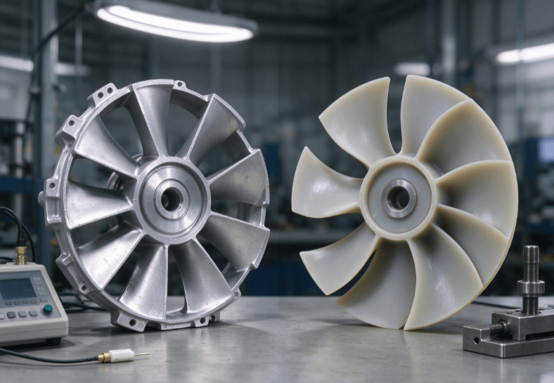
Material Selection in High-Vibration Environments
Generators expose components to continuous harmonic vibration and extreme ambient temperatures. Material failure at high RPMs causes severe internal engine damage. Proper sizing involves ensuring structural integrity under stress.
For continuous-duty outdoor power units, cast aluminum dominates. Aluminum withstands ambient heat up to 120°C and resists UV degradation. Its structural rigidity prevents blade deflection under high static pressure limits.
For standby generators or weight-sensitive enclosures, glass-reinforced polyamide (nylon) offers an alternative. Plastic composites reduce rotational inertia. This lower mass minimizes wear on the drive belts and fan clutch during startup. However, engineers must account for potential brittleness if un-treated plastics face long-term outdoor exposure.
OEM Sourcing and Custom Tooling Workflows
Standard catalog impellers rarely fit custom generator canopies perfectly. Project managers must evaluate specialized industrial axial fans tailored to specific OEM mounting brackets and drive ratios.
Initiating a factory RFQ requires precise technical data. Procurement teams must provide the required RPM, hub diameter, and maximum noise limits in decibels (dB). Custom blade profiles often require the supplier to develop new tooling molds.
B2B buyers should evaluate the following during procurement:
- Tooling lead times (typically 4–6 weeks for custom cast molds).
- Minimum Order Quantity (MOQ) policies for pilot testing runs.
- Dynamic balancing capabilities according to ISO 1940 standards.
- Availability of tapered, straight, or custom splined bore hubs.
Evaluating a supplier’s production testing capability mitigates supply chain risks. Reliable OEM partners conduct comprehensive wind tunnel testing to validate the fan’s performance curve before mass production begins.
FAQ
Q: What is the ideal tip clearance for a heavy-duty cooling fan?
A: Engineers typically aim for a tip clearance of 1% to 2% of the fan’s total diameter. Maintaining this tight gap prevents air from blowing back over the blade tips, which ensures maximum static pressure delivery.
Q: How does blade count affect noise in power generation?
A: Increasing the number of blades allows the fan to move the same volume of air at a lower rotational speed (RPM). Lowering the RPM significantly reduces acoustic noise, which is critical for noise-compliant residential generators.
Q: What technical specifications are required for an OEM RFQ?
A: A complete RFQ should include the target CFM, static pressure resistance, operating RPM, maximum ambient temperature, and specific hub mounting dimensions. Providing constraints on parasitic load also speeds up the engineering process.
Q: Can plastic blades withstand heavy industrial use?
A: Yes, if properly engineered. High-grade glass-reinforced polymers, like PA66, handle significant stress and offer lower rotational mass. However, extreme heat or heavy UV exposure often necessitates upgrading to cast aluminum.
Reference Sources
- AMCA Publication 210 – Laboratory Methods of Testing Fans for Certified Aerodynamic Performance Rating
- ISO 1940-1: Mechanical vibration — Balance quality requirements for rotors in a constant (rigid) state
- ASHRAE Handbook – HVAC Systems and Equipment (Industrial Ventilation Systems)
- Society of Automotive Engineers (SAE) – Thermal Management in Heavy-Duty Diesel Applications