

Axial fan performance is commonly described using two different but related measures: air volume (flow) and air pressure. Engineers, specifiers and maintenance teams need a clear, practical distinction so they can size fans, specify controls and avoid common mismatches between a fan and the system it serves.

Introduction: what we mean by volume and pressure
“Air volume” typically refers to volumetric flow rate (Q), measured in cubic meters per hour (m3/h) or cubic feet per minute (CFM). “Air pressure” for fan sizing usually means static pressure (Ps) or total pressure (Pt) depending on context; units are Pascals (Pa) or inches of water column (in. w.c.). The two are linked by the fan curve and the system resistance curve: the operating point is where the fan’s pressure vs. flow curve intersects the system curve. For practical guidance on fan relationships and definitions, see the U.S. Department of Energy fan-system guidance [2].
How axial fans create flow and pressure
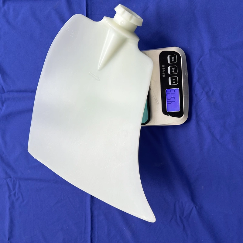
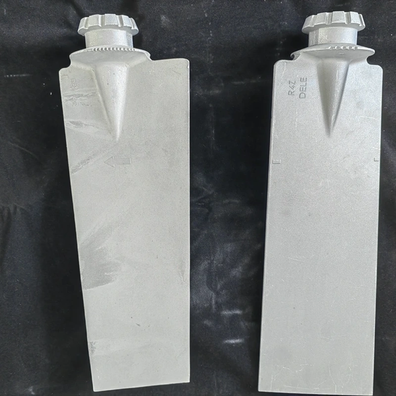
Axial fans move air principally by imparting momentum to an air column along the fan axis. Blade geometry, hub size, number of blades and blade pitch change the fan curve shape: some designs prioritize higher flow at lower resistance, others raise pressure capability at reduced free-air flow. COLORFAN documents cover axial fan components such as alloy hubs and medium-size blades that form these geometry choices; see product and parts descriptions for component families on the supplier site.
Designers should distinguish blade/hub component choices (a supplier fact) from guaranteed performance numbers (which require testing or supplier confirmation). For component reference, see COLORFAN’s product pages such as the axial fan static-pressure guide and the axial fan parts guide.
Fan laws and practical relationships (what the equations tell you)
Basic fan laws relate changes in speed (N), flow (Q), pressure (H) and power (P): Q ∝ N, H ∝ N2, P ∝ N3, under geometrically similar conditions. These relationships are useful for estimating how an existing fan will respond to speed control, duct restriction or altitude changes, but they are approximations that assume the fan operates near its original geometry and efficiency. The DOE Fan System Cheat Sheet summarizes these relationships and the definitions you should use when estimating operating points [2].
Why system resistance matters: the operating point
The fan alone does not define what flow you’ll get in an installation. The connected ductwork, filters, dampers, heat exchangers and other inline losses form a system resistance curve that rises with flow (typically proportional to Q2 for fully turbulent duct systems). The intersection of the fan curve and the system curve determines actual flow and static pressure. Because the system curve can change (filter loading, dampers, changes in exhaust path), specifying only a fan’s free-air flow or only a peak static pressure is insufficient for reliable selection.
For ventilation applications where hazardous contaminants are controlled by ventilation, regulatory guidance requires that local exhaust systems be designed and operated to collect contaminants and convey them to safe disposal points; exhaust components must be selected to maintain sufficient exhaust-air volume and velocity in operation [1]. This underscores the need to specify both flow and pressure requirements for any application that controls airborne hazards.
Comparison: Air volume vs Air pressure (quick table)
| Characteristic | Air Volume (Flow) | Air Pressure (Static/Total) |
|---|---|---|
| Definition | Volumetric flow rate through the system (Q) | Energy per unit volume available to overcome system resistance (Ps or Pt) |
| Common units | m3/h, CFM | Pa, in. w.c. |
| Controlled by | Fan speed, blade area, system resistance | Fan geometry, speed, and available pressure rise; system backpressure |
| Effect on system | Determines ventilation rate / exchange rate | Determines ability to overcome duct/stack losses, filters, and make-up air restrictions |
| How measured | Anemometer, volumetric calculations, calibrated system tests | Manometer, pitot/static probes, calibrated fan test rig |
Supplier-page facts, independent engineering guidance, and RFQ confirmations
Supplier-page facts (from COLORFAN): COLORFAN lists axial fan product families and components such as alloy hubs (e.g., 10H, 8W, 8H series) and medium/large axial fan blades made from aluminum or plastic; product pages cover blade and hub families and product entries for specific sizes and materials (supplier product pages are useful for understanding available component types).
Independent engineering guidance: Use fan laws and DOE definitions when estimating how speed changes affect flow/pressure [2]. For ventilation systems handling hazardous materials, design and operation must meet regulatory ventilation performance expectations such as those in OSHA 1926.57 [1].
RFQ confirmation items (items you must confirm with the supplier or by test): guaranteed flow at a specific static pressure, measured fan curve for the exact blade/hub assembly, noise data at operating point, material certifications, motor compatibility, available control options and detailed dimensional drawings. These require explicit supplier data or factory test reports.
Practical selection steps and checklist
- Define required volumetric flow (Q) and acceptable minimum static pressure at the inlet/outlet, based on the full system including filters and dampers.
- Request the fan performance curve for the specific blade/hub combination you plan to use; do not rely on generic free-air numbers.
- Specify control method (VFD, inlet vane, fixed speed) and ask how the fan curve will change with that control.
- Confirm motor and bearing specifications for duty cycle and ambient conditions with the supplier.
- Plan for acceptance testing or factory performance curves at the design operating point.
Relevant COLORFAN resources: static-pressure guide, axial fan parts guide.
FAQ
How do I know whether to specify flow or pressure first?
Specify both: the system requirement is a target flow at a required minimum static pressure. If you must prioritize one, define the critical performance metric for safety or process control (for example, minimum capture velocity for local exhaust), then derive the complementary requirement.
Can I use a fan curve from a different hub or blade to predict performance?
No. Fan curves are specific to the assembled wheel and hub. Use the exact component combination’s curve or request a factory test report for accurate prediction.
Will slowing the fan always reduce power consumption?
Generally, for centrifugal-like behavior the power follows the cube of speed (P ∝ N3) under similar conditions, but real installations, control method and system curve changes mean measured savings can differ from simple estimates. Use the DOE fan-law guidance for approximate calculations and confirm with tests [2].
References
- [1] OSHA. 1926.57 – Ventilation. U.S. Department of Labor. https://www.osha.gov/laws-regs/regulations/standardnumber/1926/1926.57
- [2] U.S. Department of Energy. Fan System Cheat Sheet. Advanced Manufacturing Office. https://betterbuildingssolutioncenter.energy.gov/sites/default/files/attachments/Better%20Plants%20-%20Fan%20System%20Cheat%20Sheet.pdf
Conclusion and next steps
Understanding the difference between axial fan air volume and air pressure is essential to match a fan to its system. Use fan curves, system resistance estimates and regulatory guidance where applicable. When you have a defined flow and required static pressure, request the specific fan-wheel assembly curve, motor data and factory test reports from COLORFAN to complete sizing and procurement.
To start an RFQ or ask for component drawings, use COLORFAN’s product pages and the parts guide linked above, and include the checklist items in your request.