

Engineers frequently prioritize volumetric airflow when designing thermal management systems. However, ignoring system resistance often causes catastrophic equipment failure. Understanding axial fan static pressure is critical for proper industrial cooling.
When air moves through filters, heat sinks, or ducting, it encounters friction. This friction creates severe backpressure that the cooling fan must overcome. Without adequate pressure capabilities, the system will experience complete thermal breakdown.
Many procurement teams mistakenly purchase fans based solely on CFM ratings. This oversight leads to inadequate cooling once the fan is installed inside enclosures. Airflow in a vacuum behaves entirely differently than airflow through dense machinery.
This guide explains how to evaluate system impedance for manufacturing projects. We will cover aerodynamic limitations, material selection, and proper calculation methods. Mastering these concepts ensures reliable long-term performance for automated systems.
What Is Axial Fan Static Pressure and Why Does It Matter?
Static pressure represents the physical resistance to airflow within a confined system. It is the raw force required to push air through internal obstacles. Common measurement units include inches of water column or metric Pascals.
In a completely open space, a fan operates at maximum free airflow. Under these conditions, the measured static pressure is exactly zero. As you add structural components like louvers or filters, system impedance rapidly increases.
The fan must generate enough forward force to maintain continuous air movement. If system resistance exceeds the fan’s maximum pressure rating, airflow stops completely. The blades will simply churn the air without moving it through the enclosure.
This condition severely damages internal electrical components due to localized overheating. Heat sinks become useless if forced convection cannot breach the thermal boundary layer. Proper pressure management is the only way to guarantee thermal stability.
| Metric | Definition | Engineering Impact |
| Static Pressure | Potential energy overcoming system resistance | Determines if air can pass through dense filters. |
| Velocity Pressure | Kinetic energy of the moving air stream | Dictates the speed of internal heat dissipation. |
| Total Pressure | Sum of static and velocity pressures | Used for overall fan efficiency calculations. |
The Physics of Aerodynamic Stall and Boundary Layers
When backpressure becomes exceptionally high, air detaches from the blade’s surface. This detachment destroys the smooth boundary layer required for efficient air pumping. The resulting violent turbulence creates a phenomenon known as aerodynamic stall.
During a stall, the axial fan static pressure capability suddenly collapses. Motor RPM might actually increase due to the sudden loss of aerodynamic load. However, the actual volumetric air delivery drops to near absolute zero.
Vibrations increase drastically when a fan enters this unstable aerodynamic state. These high-frequency vibrations cause premature bearing wear and mechanical fatigue. Over time, this leads to catastrophic motor failure and unplanned factory downtime.
Engineers must study the manufacturer’s fan curve to avoid this operating region. The noticeable dip in the performance curve clearly marks the stall zone. Safe system design always keeps the operating point far away from this dip.
How Blade Material Impacts Aerodynamic Stability
Under high-pressure conditions, fan blades face severe and continuous mechanical stress. The material must resist physical deflection to maintain the designed attack angle. If a blade bends, the pressure delivery drops immediately and unpredictably.
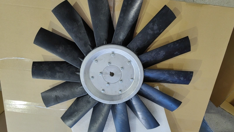
Aluminum blades offer exceptional structural rigidity for high-impedance thermal systems. They withstand continuous backpressure without warping, creeping, or losing their geometric profile. This makes metal housings ideal for dense industrial environments and harsh outdoor climates.
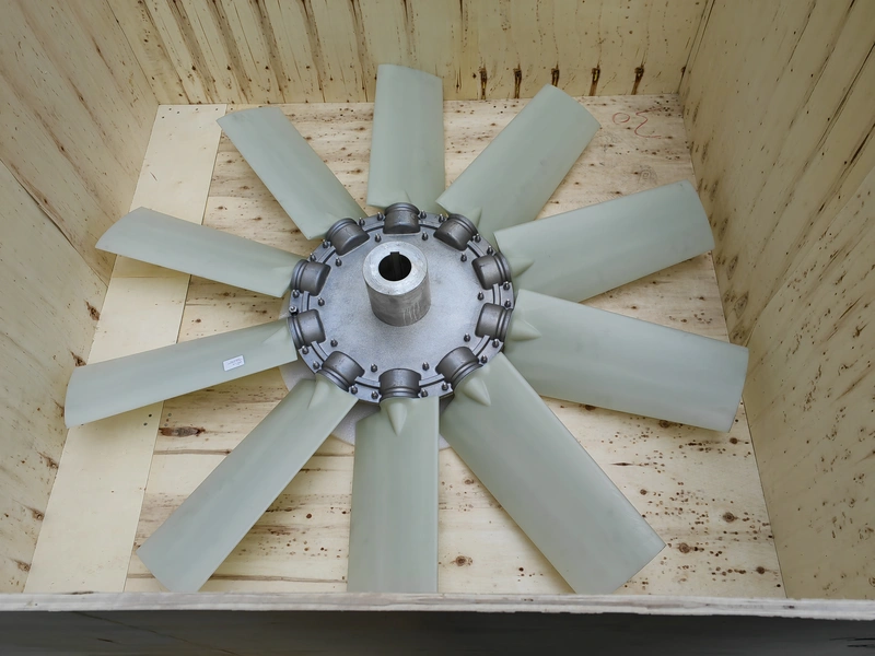
Plastic polymers provide excellent lightweight efficiency for lower-pressure cooling applications. They perform exceptionally well in standard enclosures where internal impedance remains manageable. Advanced injection molding allows for complex geometries that improve aerodynamic efficiency.
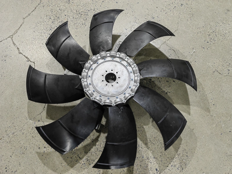
Blade shape heavily influences how the material handles system resistance. Sickle-shaped designs help reduce air turbulence and minimize acoustic noise emissions. Straight, paddle-style blades typically generate higher raw pressure but consume more electrical power.
Application Environments: Where Static Pressure Defines Performance
Different manufacturing industries dictate entirely different pressure baseline requirements. A telecommunications server rack needs distinct fan parameters compared to factory exhaust systems. Matching the operational environment to the pressure curve is standard engineering practice.
Hazardous environments often require thick, highly dense filtration systems to capture particulates. Fans must push air through these restrictive barriers without losing velocity. Maintaining consistent pressure prevents dangerous gas accumulation in these volatile zones.
Outdoor equipment cabinets face high ambient wind loads and tight internal spacing. Fans here must overcome both external wind resistance and internal component density. Properly sized pressure capabilities ensure uninterrupted operation during severe weather events.
Electronic enclosures heavily rely on tightly spaced extruded aluminum heat sinks. Forcing air through these narrow fins requires significant static pressure. A standard low-pressure fan will simply bounce air off the front face.
How to Calculate Axial Fan Static Pressure for Enclosures
Accurate calculation prevents critical undersizing and inefficient energy consumption. The system impedance curve dictates the exact pressure needed at specific airflow rates. Engineers use standard fluid dynamic formulas to plot this crucial operational curve.
The fundamental formula involves multiplying the pressure drop constant by the airflow squared. This relationship means that doubling the airflow requires four times the pressure. Engineers must account for this exponential growth during system scaling.
Every internal filter, duct bend, and heat sink adds a specific pressure drop. You must aggregate these individual resistance values to find total system impedance. Component manufacturers usually provide this drop data in their technical specification sheets.
Once the system curve is plotted, overlay it with the fan performance curve. The exact intersection point represents the actual operating point of your equipment. An optimal design places this point safely within the fan’s peak efficiency region.
Workflow for System Pressure Calculation:
- Identify all physical airflow obstacles within the equipment enclosure.
- Obtain the pressure drop data for each component from manufacturer specifications.
- Sum the individual pressure drops at the target volumetric airflow rate.
- Plot the resulting system impedance curve against the fan performance curve.
- Verify the operating point entirely avoids the fan’s aerodynamic stall region.
System Suitability and Application Matching Criteria
Selecting the correct fan requires matching pressure capabilities with specific manufacturing requirements. High-end cooling manufacturers offer varied structural configurations to suit different impedance profiles. Evaluating material and structural design ensures long-term operational reliability.
For heavy-duty industrial cooling, large size aluminum axial fans provide necessary rigidity. Variants like 6W or 9W models maintain precise pitch angles against significant backpressure. This guarantees highly stable performance in densely packed machinery spaces.
Medium size plastic axial fans suit moderately restricted manufacturing areas. Products featuring P4Z or 7XL sickle blade designs optimize airflow efficiency perfectly. These specialized geometries successfully minimize acoustic noise while maintaining adequate system pressure.
For volatile manufacturing sectors, specialized housings are an absolute regulatory requirement. Explosion-proof axial fans, such as P5Z models, safely overcome heavy filtration resistance. They ensure hazardous vapors are cleared without risking electrical spark ignition.
FAQ
Q1: What happens if an axial fan has insufficient static pressure?
The fan will quickly enter an aerodynamic stall state where airflow drops dramatically. The blades create localized internal turbulence instead of pushing air forward.
This lack of forward momentum leads to immediate overheating of the enclosed components. The motor may also over-rev, causing premature bearing failure and systemic breakdown.
Q2: How does blade pitch affect pressure capabilities?
A steeper blade pitch generally increases the fan’s ability to generate raw pressure. It allows the blade to take a more aggressive bite out of the air.
However, this aggressive angle also demands significantly more motor torque. Engineers must carefully balance the chosen pitch angle with overall motor power efficiency.
Q3: Can I use CFM alone to specify an industrial fan?
No, specifying by CFM without considering internal resistance guarantees system failure. The actual delivered airflow always depends entirely on the intersecting static pressure.
An unpressurized CFM rating only applies to fans operating in a complete vacuum. Both metrics are absolutely mandatory for accurate industrial thermal design.
Q4: What is the difference between Pascals and inches of water column?
Both are recognized standard units for measuring internal system resistance. Pascals are widely used in metric systems, while inches of water are imperial.
One inch of water column equals approximately 249 metric Pascals. Engineers must ensure they use consistent units when overlaying fan and system curves.
Reference Sources
- Air Movement and Control Association (AMCA) – Publication 201: Fans and Systems.
- American Society of Heating, Refrigerating and Air-Conditioning Engineers (ASHRAE) – Handbook of Fundamentals.
- ISO 5801:2017 – Fans — Performance testing using standardized airways.
- IEEE Transactions on Components, Packaging and Manufacturing Technology – Thermal Management Guidelines.